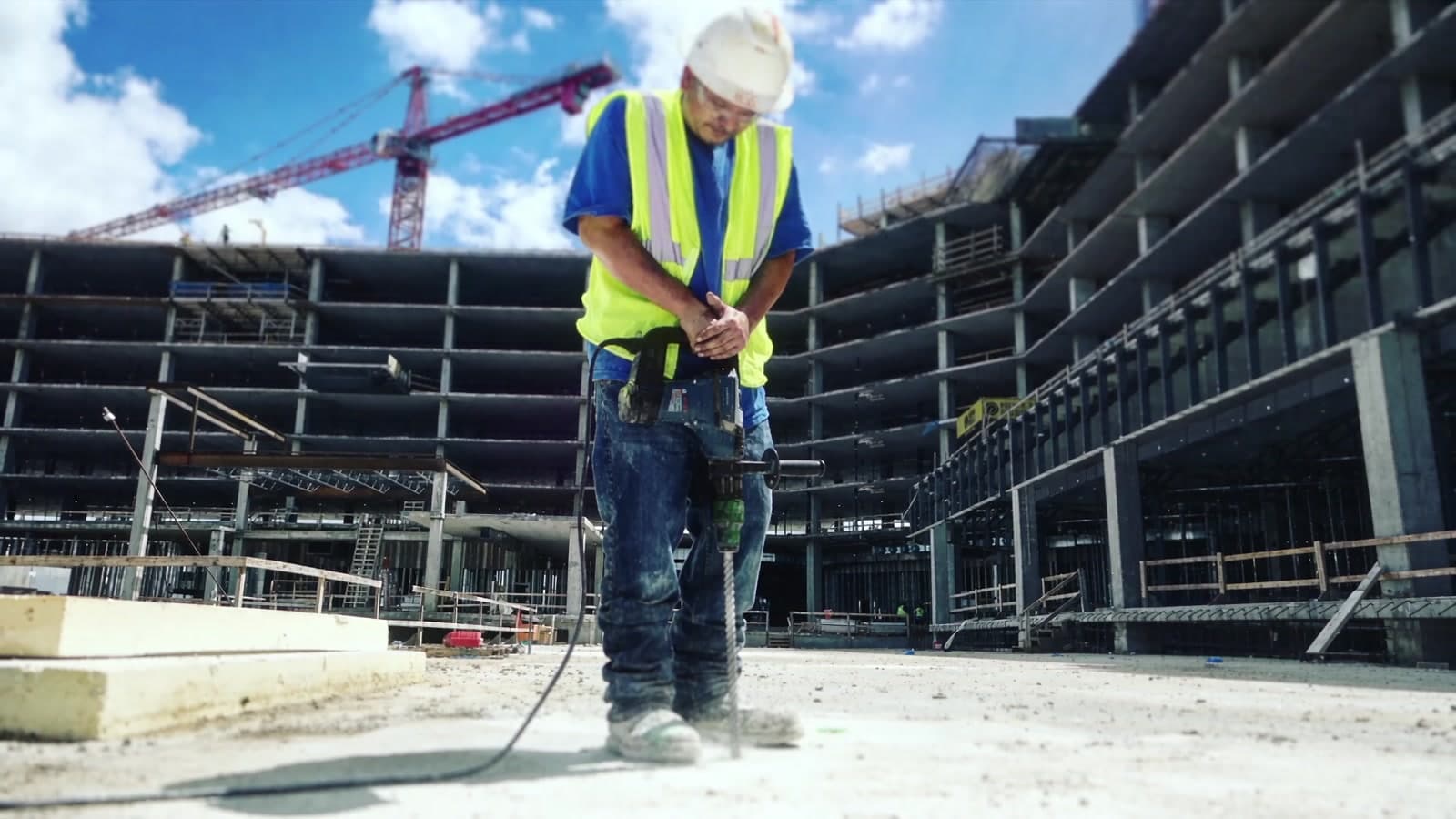
Punching Shear
Strength added at the slab-column connection, with the floor and the column left where they are.
Rebar misplacement and construction errors are never intended, but are a fact in today’s fast paced Construction Industry. The additional time and costs associated with retrofits have significant impacts to the projects and their completion. A slab-column connection short on punching shear capacity is one of the worst of them, because the traditional answer — taking out the slab and the columns beneath it — stops everything happening around it.
Reinforcement developed for the slab-column connection
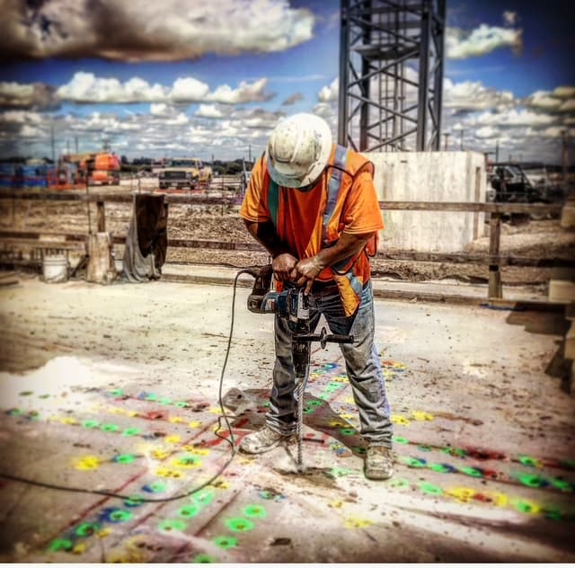
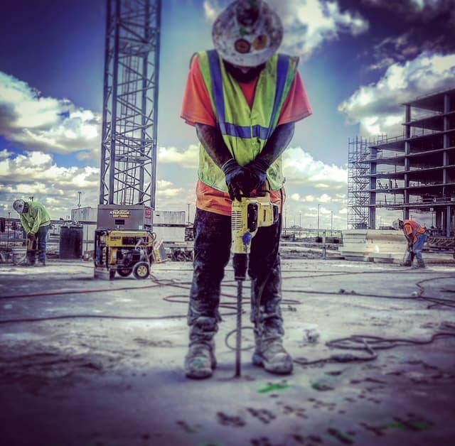
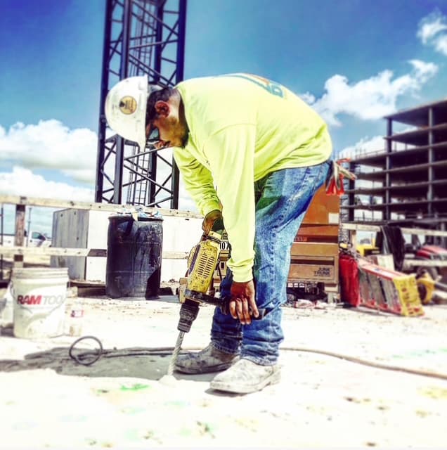
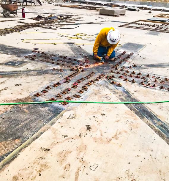
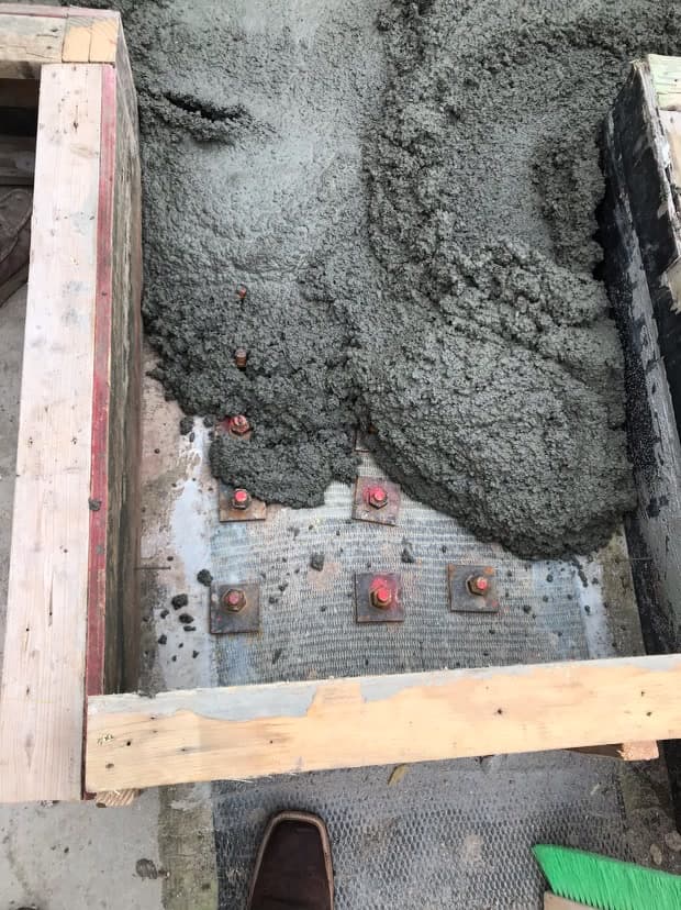
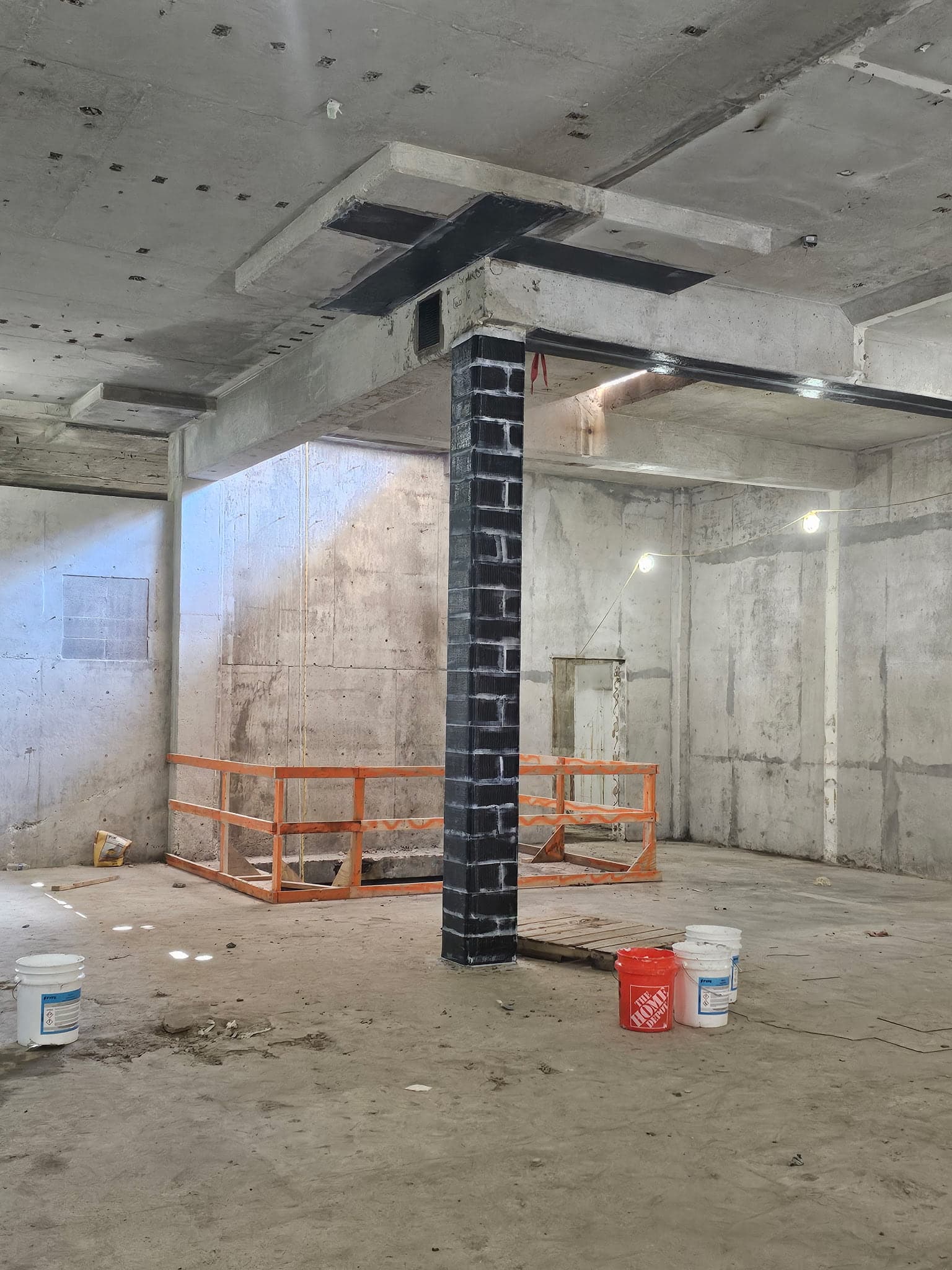
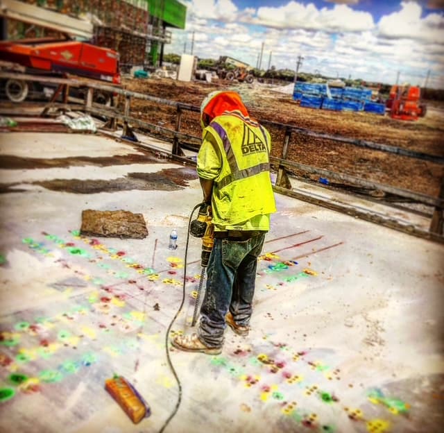
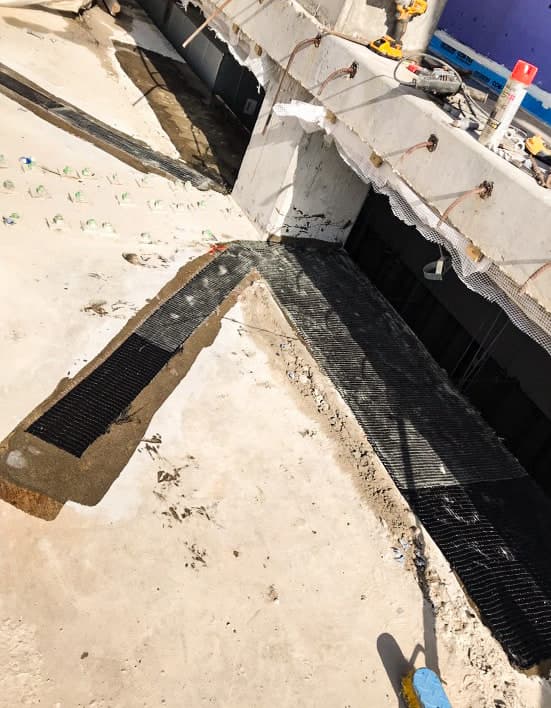
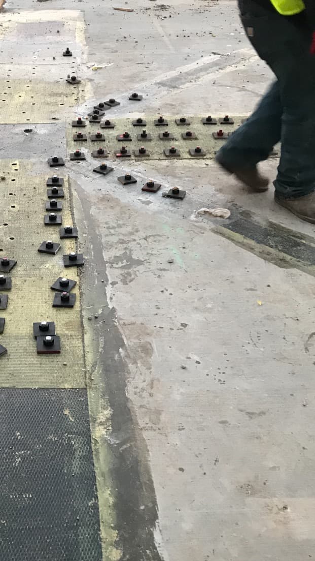
Shear bolts are a new type of reinforcement developed for punching shear strengthening and retrofit of existing slab-column connections. The shear bolt consists of a headed vertical rod threaded at the other end for anchoring using a washer and nut system. The bolt holes are drilled through the slab, layers of carbon fiber are added for strengthening, a layer of glass fiber is installed as an insulator, and the bolts are installed in holes drilled in the slab in concentric perimeters around the column.
The system is not carbon fiber alone. Its value comes from combining complementary components in a project-specific strengthening detail: externally bonded carbon fiber reinforces the slab zone, and drilled shear bolts cross the potential punching-shear surface — a coordinated, engineer-designed system installed with limited removal of existing concrete.
Why project teams consider it
- Targeted intervention. Strengthening is concentrated around the slab-column connection.
- Lower disruption potential. On the Kalahari project the method was positioned as an alternate to an original steel-beam retrofit, allowing work to proceed with less intrusive slab and column removal.
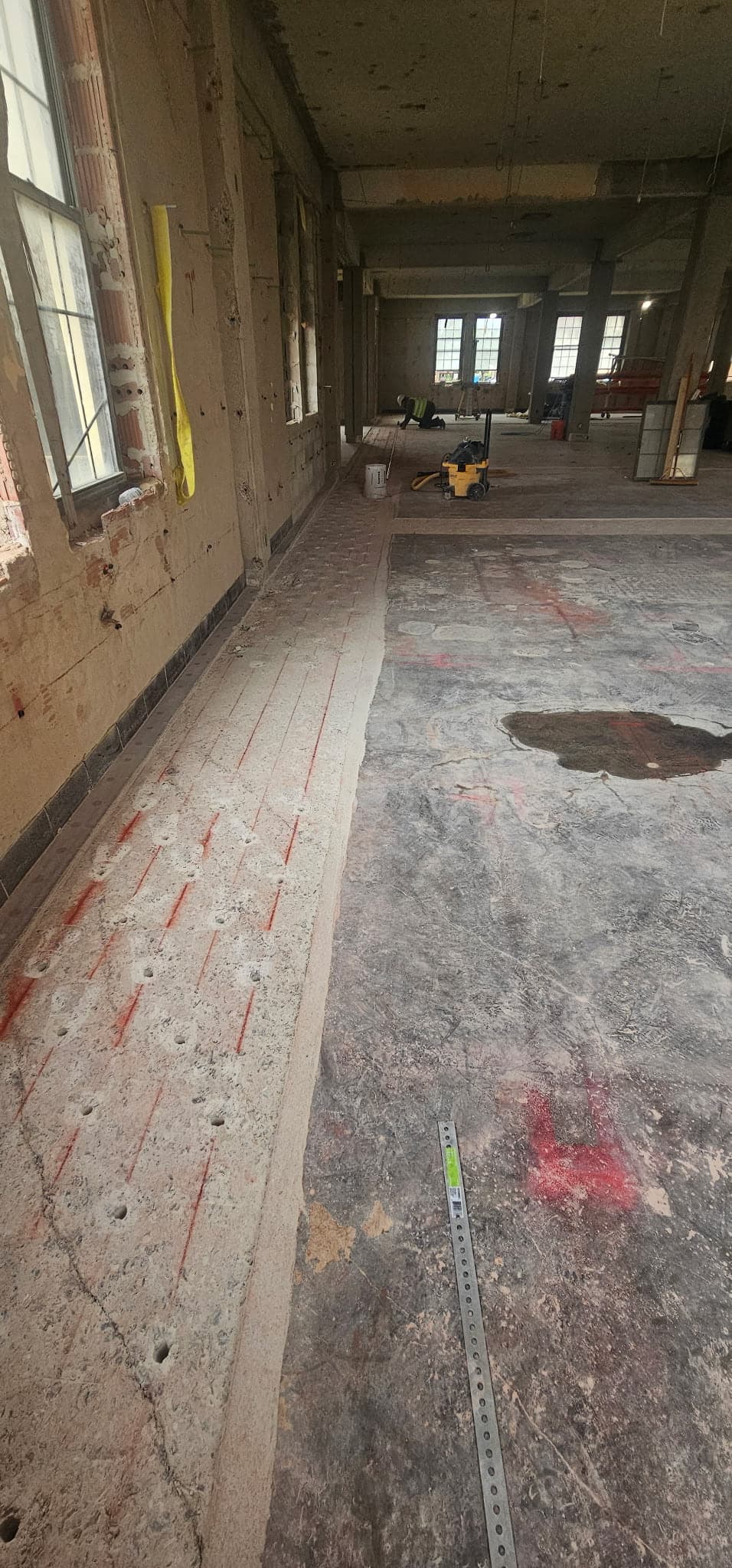
- Constructability-led layout. GPR is used to map reinforcing before holes are finalized and drilled.
- Integrated load path. CFRP supports local flexural strengthening while through-slab shear rods provide transverse reinforcement.
Where this approach fits
Potential applications include slab-column connections with punching-shear deficiencies, misplaced or cut reinforcement, changed loading, or retrofit constraints that make large steel assemblies and extensive demolition difficult.
Every installation is engineered. Existing geometry, concrete strength, reinforcement, demand, fire and environmental exposure, access, edge conditions, penetrations, and load path must be verified before construction. Final suitability, detailing, anchorage, spacing, and capacity are established by the engineer of record for the verified as-built condition.
How the retrofit goes in
A retrofit that changes the failure mode, not the building around it.
- 01
Slab Strengthening
Punching shear, shear transfer between members, negative and positive moment, new openings, and diaphragm shear strengthening
- 02
CFRP Reinforcement
Externally bonded carbon-fiber fabric strengthens the prepared slab surface in the engineered directions and extents.
- 03
Glass-FRP Separation Layer
A glass-fiber layer provides a dielectric barrier between the carbon fiber and steel components where detailed.
- 04
Drilled Shear Rods
Headed, threaded steel rods pass through the slab in engineered perimeters around the column and are secured with plates, washers and nuts.
- 05
Verified Layout and QA
GPR, field verification, substrate preparation, resin cure, drilling control, and specified tightening and torque are part of the installation plan.
- 06
Construction Errors
Supplement misplaced or cut reinforcing steel at the connection, without removing the member it sits in.
- 07
Ductility
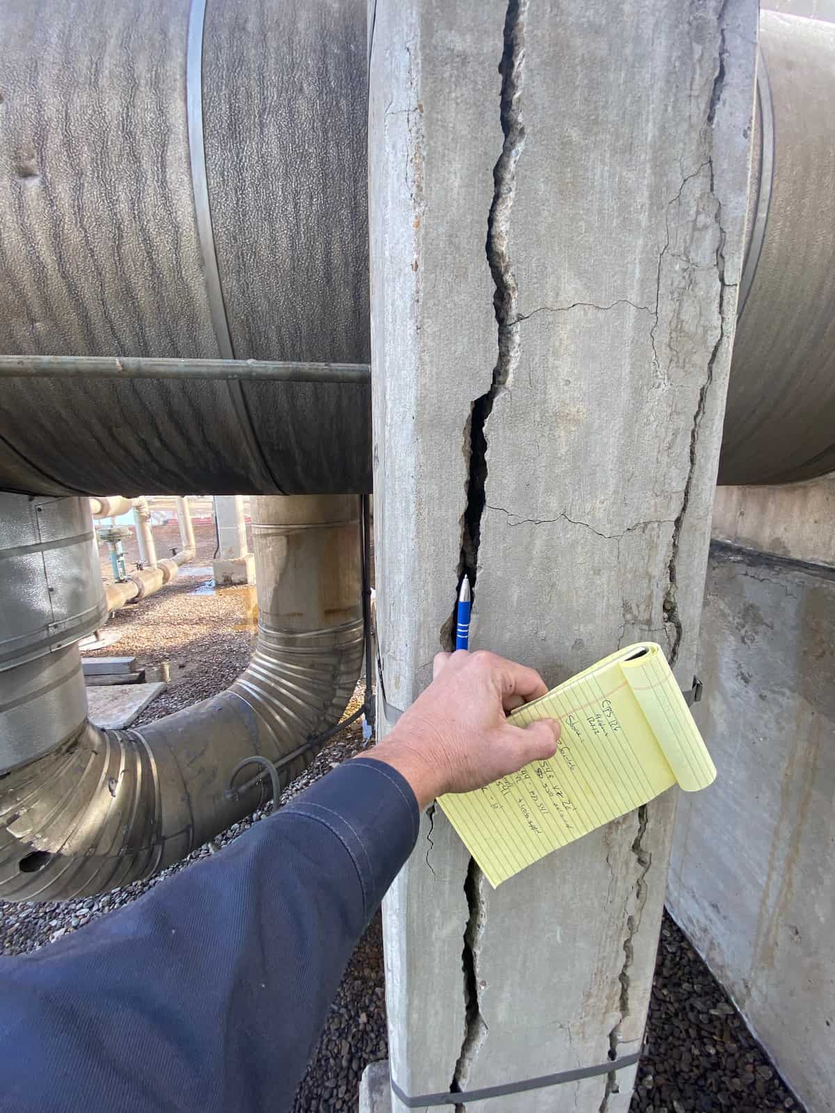
Increase sufficient to change the failure mode from punching to flexure, and to stop shear cracking propagating.
What the retrofit is designed to achieve
- Increase punching-shear resistance and ductility. The combined system performed as required for the project, and is intended to shift behavior away from a brittle punching-shear mode toward flexural response.
- Control shear-crack propagation. Shear bolts cross the potential failure surface and provide through-thickness reinforcement around the column.
- Preserve schedule and adjacent work. Targeted surface preparation, drilling, and bonded reinforcement can reduce the demolition, access, forming, welding, and replacement work of more intrusive concepts — subject to actual site conditions.
- Resolve field conflicts deliberately. Scanning and engineered hole-location limits help avoid existing flexural reinforcing; when a conflict is unavoidable, the remediation is redesigned and documented.
Advantages of CFRP Shear Bolt Retrofit Systems
- The shear-bolt retrofit system performed as required to strengthen the slab and increase ductility.
- Installation was faster and less intrusive than removing the entire slab and columns, which allowed for adjacent construction to occur.
- The shear bolts provided the required increase in strength, sufficient to change the failure mode from punching to flexure.
- Shear bolts effectively prevented propagation of shear cracking in strengthened slabs.
- The ACI code punching shear strength predictions for specimens reinforced with shear bolts and CFRP are very conservative.
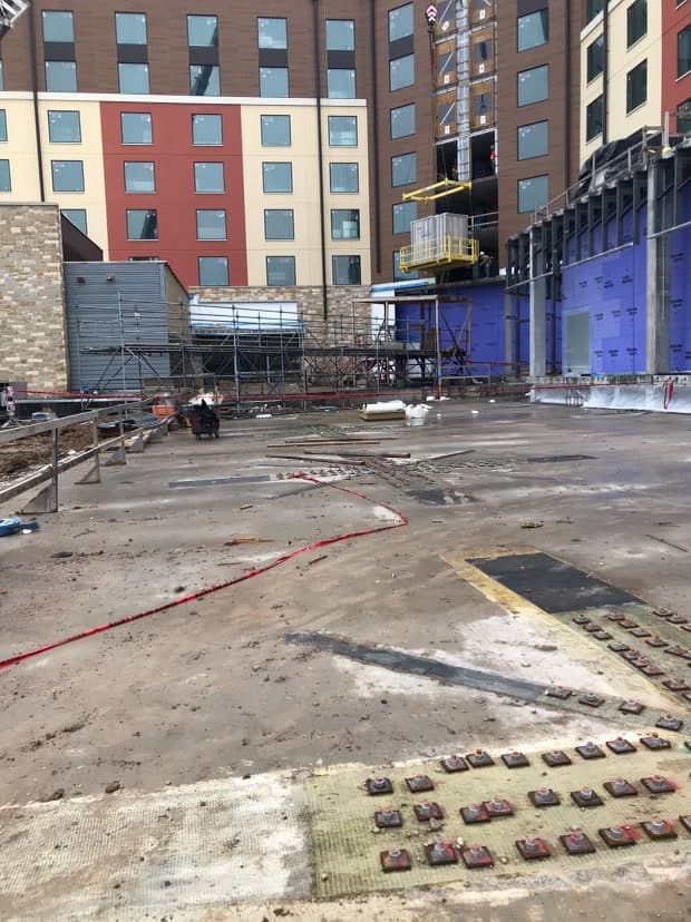
Kalahari Resorts & Conventions
The 2019 proposal identified 27 columns requiring punching-shear strengthening. It records frequent conflicts between planned drill paths and the reinforcing encountered in the slab, which increased the need for scanning, controlled layout, and engineered remediation.
Delta proposed an alternate methodology using CFRP, a glass-fiber dielectric layer, and through-slab shear rods. The project record also includes localized steel corbels where top-side obstructions prevented installation of the shear-bolt scheme — a reminder that a retrofit solution has to adapt to the constraints found in the field.
What owners and project teams gain
- A retrofit designed around access. Work can often be staged within defined slab zones while adjacent construction continues.
- Less heavy intervention where feasible. Compared with concepts requiring broad concrete removal or large steel framing, a bonded-and-drilled approach may reduce demolition and restoration scope.
- A documented path from scan to closeout. The method supports layout records, material batch and cure documentation, installation checks, and engineer observation.
- A team that can bridge design and installation. Delta coordinates constructability, specialty materials, field execution, and project-specific engineering requirements.
The engineering behind it
The Delta Structural Technology team assembled the help from Ravi Kantikar PE, Ankiet Borwanker PE, the Simpson Strong-Tie team, and Anna Polk PE, along with the research and testing done by Ms. Polk that made this project a success.
Ready to discuss a connection? Send Delta the structural drawings, deficiency or change-of-use information, available calculations, photos, and access constraints, and we can help evaluate whether a CFRP and shear-bolt concept merits project-specific engineering review.
From the field